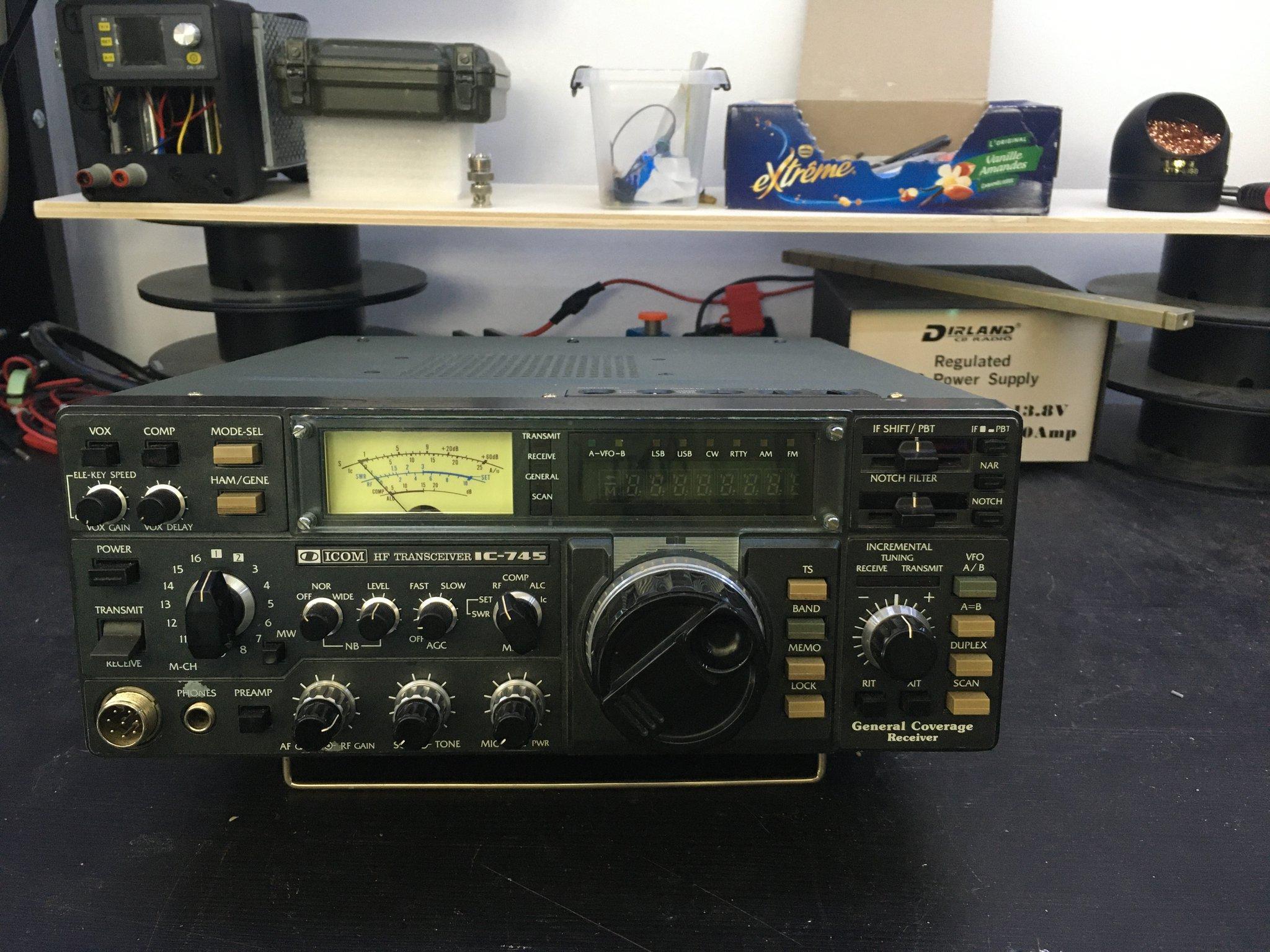
Acquired that unit with some issues, here is how im trying to make it back alive.
⚓ Infos
Installed options:
- CFW455IT AM Ceramic Filter
- CFJ455k14 SSB Ceramic Filter
- FL-30 9MHz SSB Crystal Filter
- 9M15A Crystal Filter
For some reasons, the S-METER lamp is connected directly to J1 on PLL board instead of matrix board. It is not an original mod.
TX hasn’t been tested as it’s not useful to me at all, I however have a dummy load with a tap, if I want to test it.
⚓ Memory board
I have reprogrammed the ram/memory board in hope that fixes some issues, but it didn’t.
I have built the N2CBV programmer (mirror here) with bin file from here (mirror here).
The parport needs to be in bidir IIRC and not ECP, and software be used on a computer with a real MS-DOS.
⚓ Issues
Silent means no signal but noise, dead silent is absolute silence.
- S-Meter doesn’t react to signal change
- In AM only strong signals comes through, everything else is silent
- CW is silent (related to strong signals issue ?)
- USB is the same
The modes button cycle LSB->USB->CW->RTTY and AM but AM led doesn’t lit, and pressing it further does no change, no cycle back to LSB. LSB cannot be selected because of that, unless some uninitialized memory contains it by luck.- “Filter” switch in USB has one position working, the other one is dead-silent, even though I have a filter for 9MHz SSB and one for 455KHz SSB.
- Activating the preamp seems to do more harm than good…
About the strong signal thing, in the evening I can only get strong AM broadcasts (and there isn’t a lot), I can’t hear any CW, or even one UK radio I can successfully receive with a R-2000 on the same antenna, or through a mini-whip with a rtl-sdr or airspy.
⚓ Diagnostic changelog
⚓ 26/04/2020
Spotted another broken solder joint, unplugged pll board and filter one, reconnected everything, re-soldered two RF connectors.
narrow/wide seems to switch when in AM, and effect as expected apparently, but nothing in CW.
Transistors around preamp section seems ok according to voltages, but nothing better, RX is still very quiet.
Touching alignment point for noise floor makes the S-Meter start to react (with somehow high dBm input). A full calibration seems necessary.
⚓ 25/04/2020
Problem with cycle modes/AM has been fixed.
There was no voltage present on AM pin of P19 of matrix board, no voltage on flex J1 on matrix board and flex J5 of logic board.
J5 on LB is also partly connected to J2, the AM pin on J2 had voltage, not on J5.
Cold joints of resistors around J5 were fixed, which fixed the issue with modes.
J1 (32) was unsoldered, and a new connector crimped as the old one wires broke.
⚓ 24/04/2020
Memory board card has been reprogrammed.
⚓ 11/07/2020
Tried realignment, no success.
Best AF measurement on ext speak I can get is around 170mV.
One trimmer, R141 (CW PREAMP GAIN), goes from “ok” to “murder ears”. 0.170V to 6/7V no in-between.
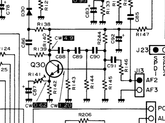
Measurements around Q30 were:
- 0.68 -> 0.987
- 4.9 -> 4.03
- 1.20 -> 1.621
Put R141 out, got around ~100R between two pins, and from 0-ish to ~100R full turn, didn’t seemed to be broken or weird values when turning.
Injecting a signal at 14.000MHz:
- -117dBm -> can’t hear at all
- -57dBm -> start to hear
- -47dBm -> can hear ok
-117dBm correspond to the -10dBµ used for TOTAL GAIN adjustment. S9 should be set with +30dBµ (-13dBm).
Still a problem:
- huge loss/attenuation of input signal
- s-meter not moving (but if reducing RF GAIN it moves as expected)
- activating preamp add even more attenuation
⚓ 11/11/2021
- J21: 8.2V on each pin relative to chassis
- Even with AF and RF gain to the max, volume through headphones isn’t that loud, could be related to R141 (CW PREAMP GAIN) (from previous tests)
- Cold solder joints on RF board fixed
A few dBm gained after cold solder joint fix but still the same issues (no s-meter movement, lots of noise even with S9/-93dBm injected on antenna input, have to bump to at least -43 or -33 to have something ~decent but still with noise)
⚓ 14/11/2021
Note: 14MHz will activate b10 (D21 in, D20 out)
- Injecting 14MHz at -63dBm
- -66dBm at point between D35 and L86
- -83dBm at out of D16 (before L17)
- -84dBm at cathode of D34
- signal too low to be detected by the TinySA on cathode of D34
- V measurements
- J10, PRI = 2.2 if preamp off, 0 if preamp on
- Q14 base is 8.2
- Q13 emitter is 12.9
- Q10 collector is 0 if preamp off, shows 0.1 very quickly when switching preamp from on to off
- Q11 drain is 13
- Q12 drain is 13
- Nothing on source of Q11 and Q12
⚓ 20/11/2021
TX test.
- switch on RX, 1.27A
- switch on TX, 3A
- RF to min, using the key switch (tip and ring) display switch to ALC, needle move to 5, increasing the RF pot reduce it. display switch on RF, nothing.
- Fan doesn’t kick on, external auto-tuner doesn’t detect any signal.